How to Program Your Robot Car into a Goalkeeper?
Programing a robot car can bring a lot of fun. In this post, we are going to discuss how to program a robot car into a goalkeeper: watching the ball, moving to the ball, kicking it, returning to the start point and waiting for the next ball, keeping itself in the field… What’s more, we will walk through the system states and transition between states below these subtasks, and principles and methods of these subtasks.
Goal
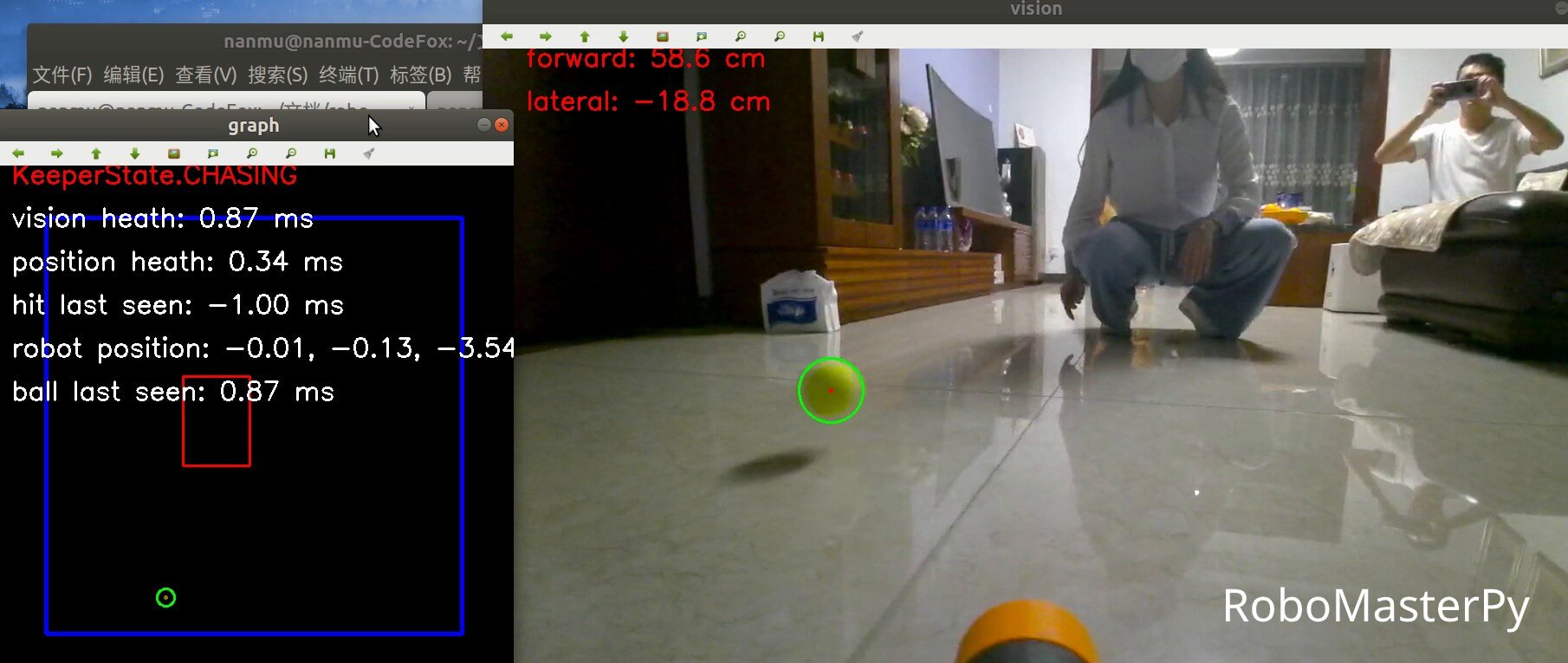
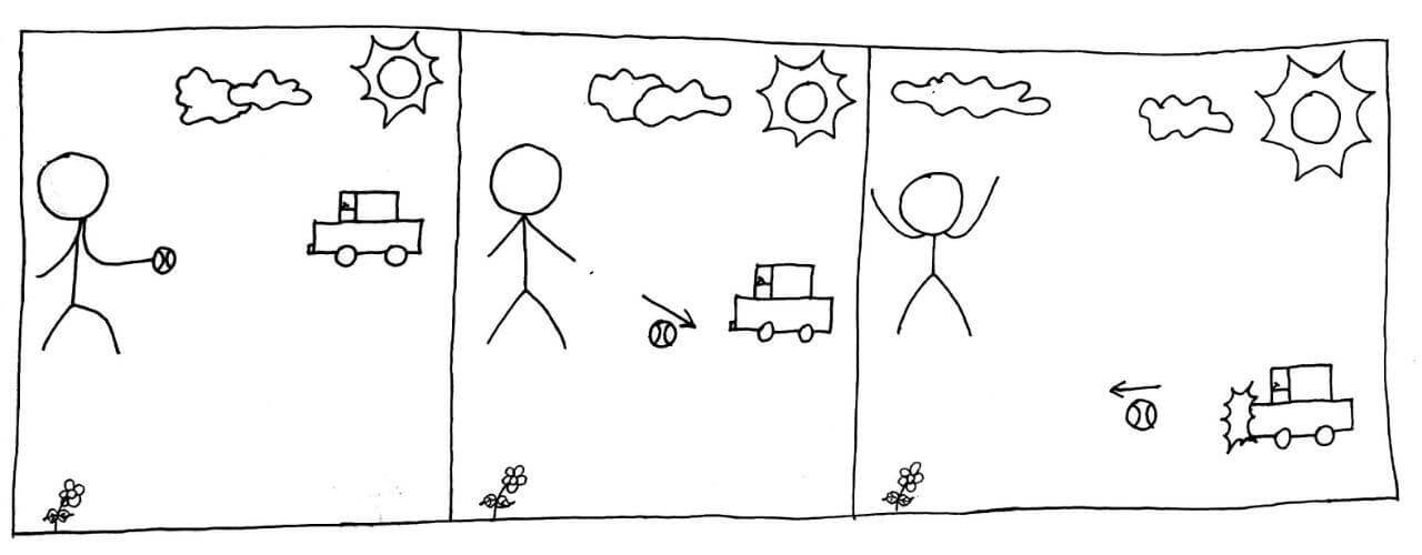
Our goal is straightforward. Pushing a tennis ball on the ground, our robot car intercepts the ball before the ball runs behind the car, and hit the ball back.
Considering the size and strength of the robot car, as well as the cost to repair, I choose not to use a soccer ball.
Device
Here the robot car I use is RoboMaster EP Core, controlled with RoboMasterPy, an unofficial SDK and programing framework, which is developed by me.
EP is driven by four Mecanum wheels, which enable it to go sideways. Developers can read(video/audio streaming, vehicle metrics, etc) and write(remote controlling) EP through its API. The chassis body is flat and smooth enough to hit the ball, and there are four hit sensors built in chassis’ front, rear, left, right sides, which are triggered during noticeable hits.
If you don’t have the same device as mine, don’t worry too much. You can still get some device-irrelevant, general ideas in this post.
Top-down Design
Overall speaking, our goalkeeper has three states: watching, intercept, kicking. Our robot car is always in one of these three states after booting, and switches its state among them if specified conditions are met.
For example, given a far-enough ball, a goalkeeper under watching mode should not rush to intercept, instead it should wait calmly for better battery life. However, when the ball is near enough, the goalkeeper should surly switch to intercept mode. Another example is that a successful intercept should result in a switch to kicking state, while a failed one results in a switch to watching state.
stateDiagram
  watch
  chase
  kick
	[*] --> watch

	watch --> chase: the ball is near enough
	chase --> watch: lost sight of the ball
	chase --> kick: ball is really close
  kick --> watch: kicked the ball or lost sight of the ball
Furthermore, there may be need to trigger some routine procedures before entering a new state, like returning to start point before entering watching state.
Finally, before starting the game, we must mark a safe zone, namely the field, to let our robot car drive freely, and ensure it runs inside the field, so as not to crash itself or other stuff.
Divide and Conquer
After clarifying the top-level requirements, let’s break down the subtasks:
- global: keep itself inside the field; figure out position of the ball;
- watching: return to start point before entering watching state;
- intercept, kicking: move to the ball;
Next, we will analyze each subtask, from the easy to the hard.
Return to Start Point and Keep itself in the Field
This subtask is not as difficult as it seems, thanks to the built-in function of my device.
We define the field as a rectangle, whose geometric center(here we call it origin) is where the robot car gets booted. RoboMaster has a built-in odometer, which provides current coordinates $(x, y, z)$ relative to the origin, namely forward distance, rightward distance and clock-wise rotation angle. We simply pull the coordinates once in a while, and order our goalkeeper return to the start point when it runs out of bounds, which is:
For a field with depth $D$, width $W$, if $\mid x \mid > W / 2$ or $\mid y \mid > D / 2$, we order the robot car to move $(-x, -y, -z)$.
During implementation, I found there is some drift in the odometer, thus every measure differs a little although our robot car keeps still. Furthermore, the robot car has its precision limit, does not handle tiny movement very well(Think of 0.06 cm forward, -0.02 cm rightward, -0.37° clock-wise). So we optimize our decision logic to:
If $\mid x \mid - W / 2 > \epsilon_{distance}$ or $\mid y \mid - D / 2 > \epsilon_{distance}$, we make robot car move $(-x, -y, 0)$, meanwhile, if $\mid z \mid > \epsilon_{degree}$, we make robot car rotate to the angle when it boots, where $\epsilon_{distance}$ and $\epsilon_{degree}$ are individually the minimal distance threshold and minimal degree threshold to return to origin. For my device, they are individually 1 cm and 2°.
Move to the ball
Our goalkeeper moves to the ball during intercept and kicking. For simplicity, goalkeeper moves only sideways(leftward/rightward) during the intercept state, moves forward and sideways during the kicking state.
Intercept
My initial solution is to collect the ball’s positions within a past, small period, and draw a line fitting these positions, intersecting with the goal. The intersection is where our goalkeeper should rush to and wait.
This solution has too many flaws:
- It’s non-trivial to obtain the ball’s position relative to the field;
- The ball does not necessarily move in a straight line because of rotation, slipperiness, bump on the ground. The car also runs in a curly line in the same way.
To intercept the ball reliably, we must control the vehicle continuously, with each step considering the output of last step. This way of control is named as Closed-loop Controller.
Since it’s not easy to estimate the ball’s position on the field, let’s use the lateral position error of the ball relative to the car $\Delta y$ as the control input instead, and the lateral speed of the car $v_y$ as the output. The control function $v_y = f(\Delta y)$, after entering $\Delta y$, gives $v_y$, at the speed of which the car will travel. We expect $\Delta y$ tends to 0 after multiple rounds of control, meaning the car is at the same position and speed relative to the ball in the lateral position. When implemented, the control frequency is about 10 times per second.
So, how to find $f$?
The simple idea is to multiply $\Delta y$ by a constant:
$$f(\Delta y) = K_p \Delta y$$
As we want to make $\Delta y$ tend to 0 we need $K_p > 0$, so that when the ball is on the right side of the car, the car’s speed is to the right, and the more the ball is on the right, the higher the speed the car moves. This way is called Proportional Controller.
Proportional controller takes into account the current error $\Delta y$, but this is not enough. A savvy goalkeeper must also consider the error of the past and the future. What we need is PID Controller(Proportional-integral-derivative Controller):
$$f(\Delta y) = K_p \Delta y + K_i \int_0^t \Delta y \cdot dt + K_d \frac{d}{dt} \Delta y$$
Among them:
- $t$ is the time;
- $K_p, K_i, K_d$ are the coefficients of proportional unit, intergral unit and differential unit respectively;
- $\Delta y$ is the current error of the system;
- $\int_0^t \Delta y \cdot dt$ stands for the error of the past;
- $\frac{d}{dt} \Delta y$ stands for the error of the future.
It’s okay, no worry about math. If you are using Python, simple-pid is a neat PID controller implementation.
Once $f$ is determined, the interception process is relatively clear:
- Obtain current $\Delta y$;
- Calculate $v_y = f(\Delta y)$, update the lateral speed of the trolley to $v_y$;
- Go back to step 1 and repeat.
After determining the appropriate coefficient of $K_p, K_i, K_d$ according to the intrinsic attributes of the vehicle and the ground, out goalkeeper can intercept the tennis ball now!
Kick
The core of kicking is when to kick and how much speed should the vehicle run at.
In my approach, our goalkeeper enters kick mode when the ball is 0.3 m away in the forward direction. During this mode, the vehicle’s lateral speed is kept at the final speed of previous interception mode, and the forward speed is manually set to 0.4 m/s.
Why is it 0.3 m? The tennis ball disappear from view if it gets closer. Due to the vehicle’s intrinsic structure and the position of its camera, unfortunately our goalkeeper can not see what is in rightly front of it. Well, image a guy with a huge beer belly, trying to look down at his feet while standing up and straight…
During the whole kick mode, our goalkeeper assumes the lateral position of the ball to itself stays unchanged since there’s no view of the ball. This assumption lasts up to 3 seconds.
Where is the ball?
Here finally comes the highlight. In this section, we will discuss how to determine the position of the ball relative to the vehicle, so as to determine $\Delta y$ and $\Delta x$ mentioned above.
Ball’s Position in the Picture
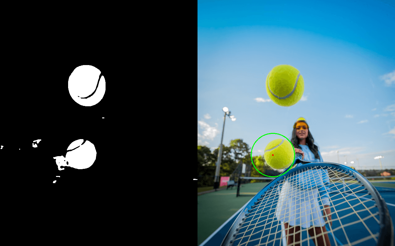
The vehicle reports everything it sees through the video stream, which actually consists of frames of images. Now, how to locate a tennis ball in an image?
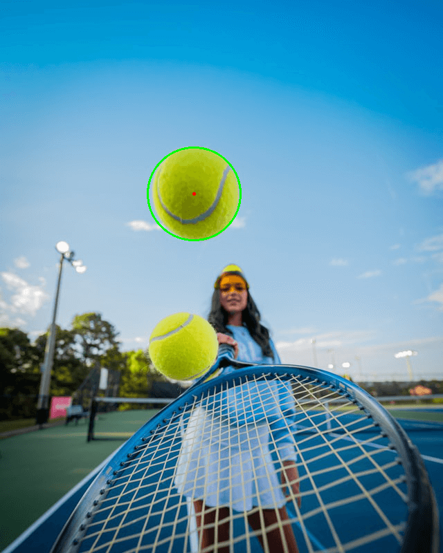
The answer is simple, let our program find and locate the largest green circle in the image.
The first step is to locate the green area of tennis in the image.
The color scheme we are used to is RGB. However, in order to make the representation of the color range easier, we use the HSV scheme, in which the color is defined by the hue, saturation and value. The following picture may bring you some intuitive feeling:
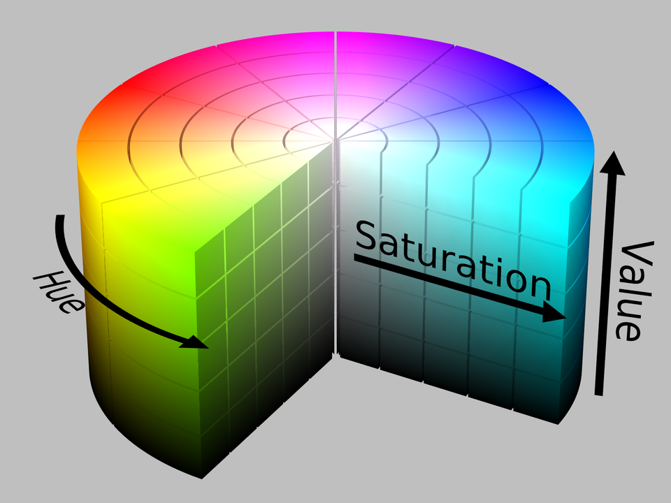
Using OpenCV to find the color in the picture whose HSV value are between $(33, 90, 90)$ and $(64, 255, 255)$ results as follows:
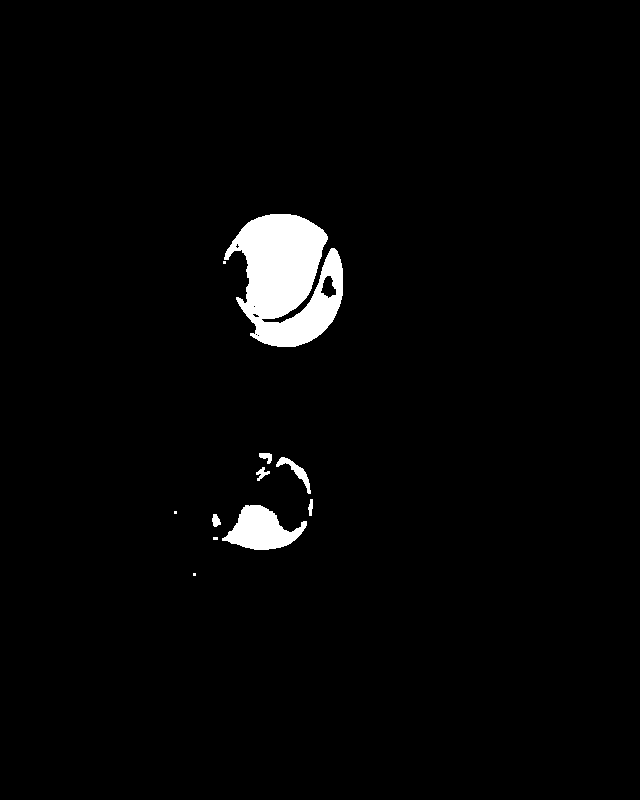
Why is the green color range defined between $(33, 90, 90)$ and $(64, 255, 255)$? This is actually based on the environment where the image was taken, by trial and error. Although the color of tennis remains the same, the color in the image is affected by factors like light, white balance, shadow, etc. The point is to find a suitable color range, which is not too narrow to pick out the ball and meanwhile too wide to misidentify other greenish stuffs as the ball.
The HSV range I am using under natural light in shade is between $(29, 90, 90)$ and $(64, 255, 255)$. You may use that as a start point for experimenting.
The second step is to find the circle.
OpenCV’s approxPolyDP() method fits each contour with a polygon with as few edge as possible. Through parameter tuning, I make the circumference length of fitted polygon differs from the original contour’s by no more than 1%. If a contour requires 8 or more edges to accomplish the fitting process, it is regarded as a circle.

Now we can locate green circle in the image. After omitting green area that’s too small or too big(usually, they are stuffs in the background), taking the contour with the greatest number of fitting edges, and calculating its circumscribed circle with OpenCV’s minEnclosingCircle() method, we have the position of the tennis ball $(x_{pic}, y_{pic})$ and radius $r_{pic}$ in the image.
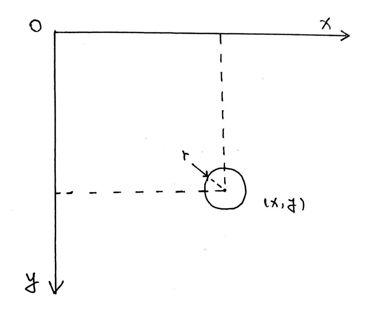
It is worth noting that the origin of the coordinate system in the image is in the upper left corner, the $x$ axis is to the right, and the $y$ axis is down.
Ball’s Position Relative to the Robot Car
Since the car and the ball are coplanar(on the same ground), the ball’s position to the car is uniquely defined by the forward distance from the car to the ball $\Delta x$ and the lateral distance from the car to the ball $\Delta y$ (positive to the right).
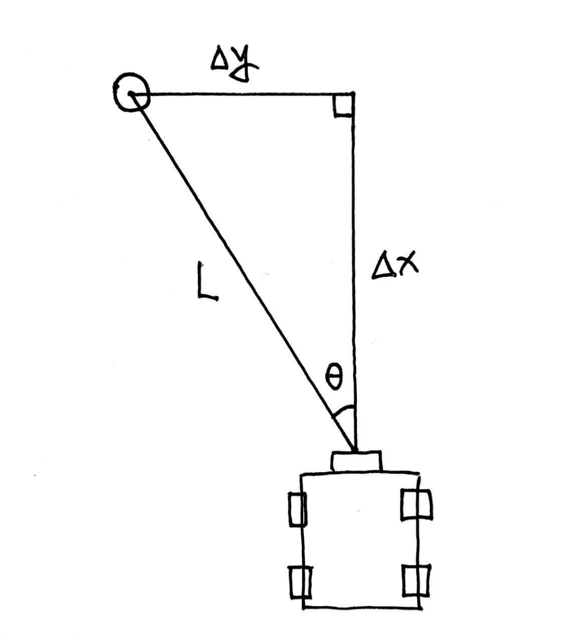
The straight-line distance from the ball to the camera of the trolley, that is, the hypotenuse of the triangle, can be calculated using the camera pinhole model:

$$\frac{actual Size Of The Object}{size Of The Object On The Camera Sensor} = \frac{distance From The Object To The Camera}{focal Length}$$
Knowing three of the four quantities can lead us to the fourth.
The size of the object on the camera sensor is proportional to the size of the object in the image. We can use a tap measure with a actual-size-known object to obtain the focal length under current resolution, by placing object and taking photo multiple times. Now, we can calculate the linear distance between the tennis ball and the camera $L_{actual}$:
$$L_{actual} = K_{camera} \cdot \frac{r_{actual}}{r_{photo}}$$
where K_{camera} is the focal length under current resolution.
The horizontal angle of view of the camera of my device is 96°. To simplify the problem, we believe that the horizontal angles are evenly distributed along the $x$ axis. At this time, the yaw angle of the tennis ball to the car $\theta_{yaw}$ is:
$$\theta_{yaw} = 96 \cdot (\frac{x_{photo}}{X_{photo}} - 0.5)$$
where $X_{photo}$ is the horizontal pixel number in the photo. Mine is 1280.
Finally, the forward distance $\Delta x$ and lateral distance $\Delta y$ from the car to the ball can be solved as:
$$\begin{aligned}\Delta x &= L_{actual} \cdot \cos\theta_{yaw}\\ \Delta y &= L_{actual} \cdot \sin\theta_{yaw} \end{aligned}$$
Top-down Design, Again
Now we have considered all subtasks above. We can draw out robot car’s state diagram with fine detail:
stateDiagram
  watch
  chase
  kick
	[*] --> watch

	watch --> chase: the ball is within 1.2m to the car
	chase --> watch: hit detected on front chassis\n lost sight of the ball for more than 3s\n the ball is more than 1.4m away\n the car is out of its field\n (match any condition)
	chase --> kick: the ball is within 0.3m
	kick --> watch: hit detected on front chassis\n lost sight of the ball for more than 3s\n the ball is more than 1.4m away\n the car is out of its field\n (match any condition)
Time to Celebrate!
After going through lots of debugging, I found it is really satisfied to play with the robot car - Our home-brewed goalkeeper is not too bad!
The code powers our goalkeeper is open sourced.
Have fun!
Acknowledgement
The work in the post was incubated during a RoboMaster developing contest. The author would like to thank DJI for hardware and technical support.
References
- https://en.wikipedia.org/wiki/PID
- https://en.wikipedia.org/wiki/Pinhole_camera_model
- https://web.stanford.edu/class/cs231a/course_notes/01-camera-models.pdf
- https://unsplash.com/photos/6D2Lmtv_X8A
- https://en.wikipedia.org/wiki/HSL_and_HSV#/media/File:HSV_color_solid_cylinder_saturation_gray.png
- https://en.wikipedia.org/wiki/Pi#/media/File:Archimedes_pi.svg
